-
- Week6 Overview
- My Personal assignment
- Software Introduction.
- Programmed My Xiao ESP32S3 Board to interact and communicate
- The programming processes & code
- Hero shots
- Team assignment
- Browse through the datasheet for your microcontroller
- Compare the performance and development workflows for other architectures.
week06-Embedded Programming
Week 6 - Overview
In Week 6 of the study, I learned about embedded programming and testing:
1. Learned about the development board I am using, the XiaoESP32S3.
2. Learned how to use the Arduino IDE.
3. Studied program structure and did some programming.
4. Tested my program.
Starting this week, we need to complete two projects: a team assignment and an individual assignment.
Group assignment:
browse through the data sheet for your microcontroller
compare the performance and development workflows for other architectures
Individual assignment:
- Write a program for a microcontroller development board that you made,
to interact (with local input and/or output devices)
and communicate (with remote wired or wireless devices)
Extra Credit:
- Use different languages and/or development environments
- Connect external components to the board
Reference Links
Week6-Embedded Programming Guide for my Fab Academy Journey.My personal assignment
1.Software Introduction
Arduino IDE:
Arduino IDE (Integrated Development Environment) is an open-source software used for writing and uploading code to Arduino-compatible boards.
It provides an easy-to-use environment for both beginners and professionals to develop various electronic and robotic projects.
```html
Main Features
- 1. Cross-Platform: The Arduino IDE can run on Windows, Mac OS X, and Linux operating systems, supporting a wide range of users.
- 2. Simple User Interface: The IDE is designed to be intuitive, primarily consisting of a code editor, message area, text console, toolbar, and buttons for compiling and uploading programs.
- 3. Built-in Example Code: It offers a variety of built-in examples that help beginners get started quickly and experiment.
- 4. Extensive Library Support: Users can easily add and utilize third-party libraries to extend the functionality of Arduino boards, such as driving sensors, controlling LEDs, connecting to the internet, etc.
- 5. Programmability: Supports programming in C and C++, allowing users to take advantage of these powerful language features to write complex programs.
- 6. Serial Monitor: The built-in serial monitor assists in debugging programs by monitoring and sending data to and from the Arduino board, checking the execution status of programs.
Development Process
The development process using the Arduino IDE typically involves the following steps:
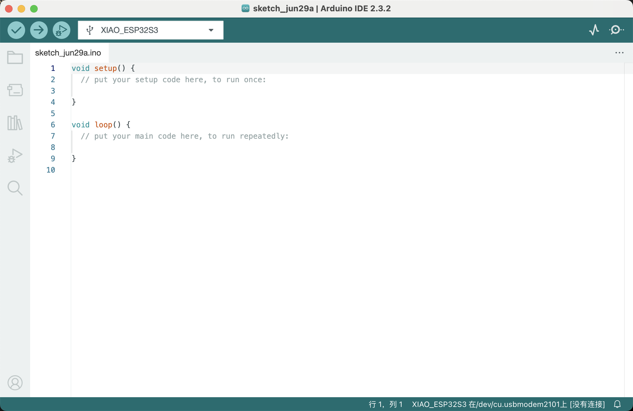
1. Writing Code: Enter your program in the code editor. The IDE provides basic text editing features like cut, copy, paste, find, and replace.
2. Compiling Code: Compile your Arduino code by clicking the “Verify” button on the toolbar. The IDE checks for errors in the code and provides necessary feedback.
3. Uploading Code: Upload the compiled code to the Arduino board. Connect your Arduino board to the computer, select the correct board type and port, and then click the “Upload” button.
4. Debugging: Use the serial monitor to view real-time outputs from the Arduino board, which helps in debugging the program.
Target Audience
The Arduino IDE is particularly suited for educational purposes, prototyping, and hobbyist projects.
It is a popular tool among educators and makers because it simplifies complex programming tasks, allowing non-programmers to easily start with electronics and programming.
Conclusion
The Arduino IDE is a powerful yet user-friendly tool suitable for users of all levels engaged in electronic project development.
Its accessibility and ease of use have enabled millions of users worldwide to turn their creative ideas into reality.
Software: Mach3
- Software to control the CNC machine, used for initializing the equipment, setting tool positions, and loading and executing G-code.
- Allows manual control of the machine’s movement and adjustment of spindle and feed rates.
2.Programmed My Xiao ESP32S3 Board to interact and communicate
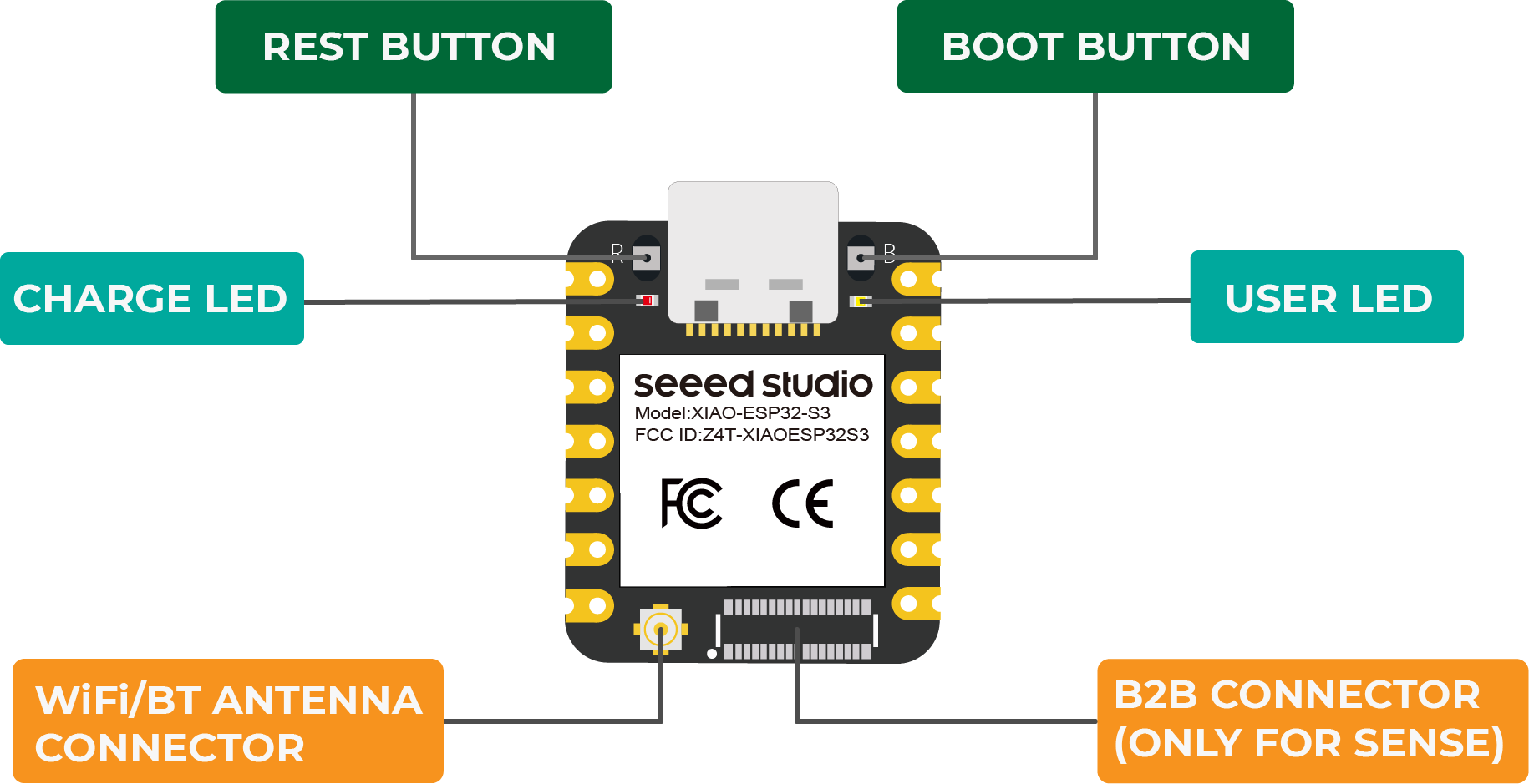
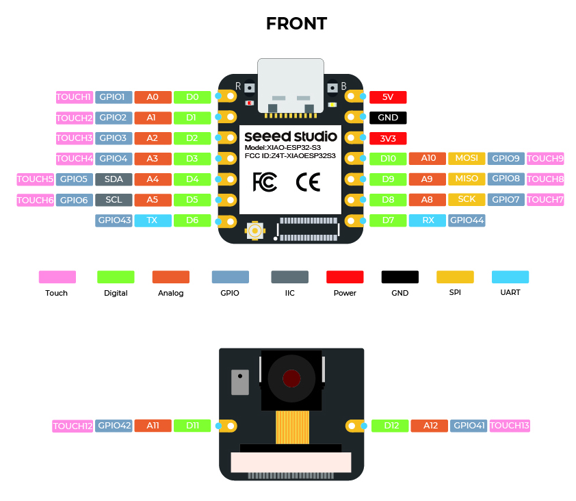
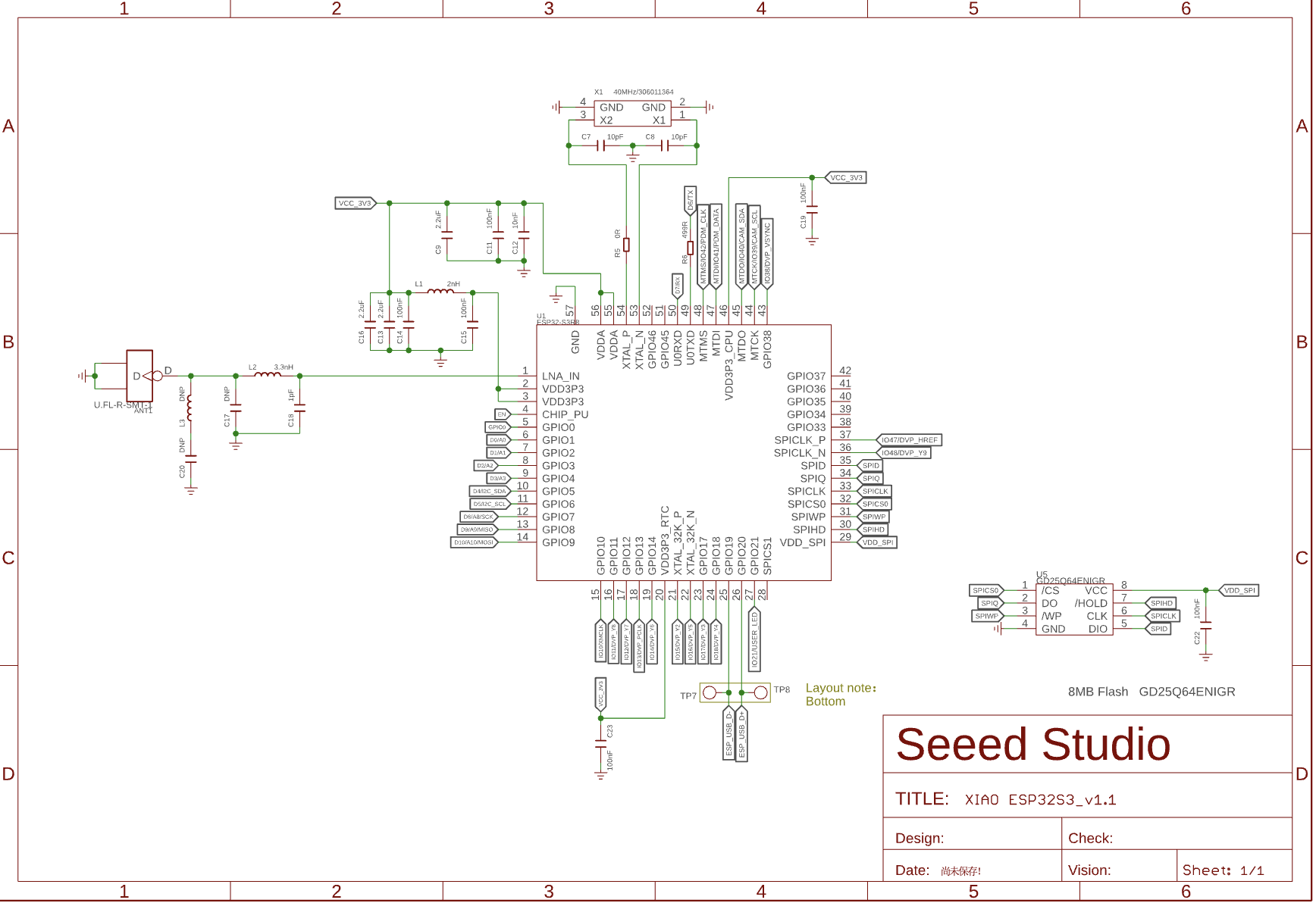
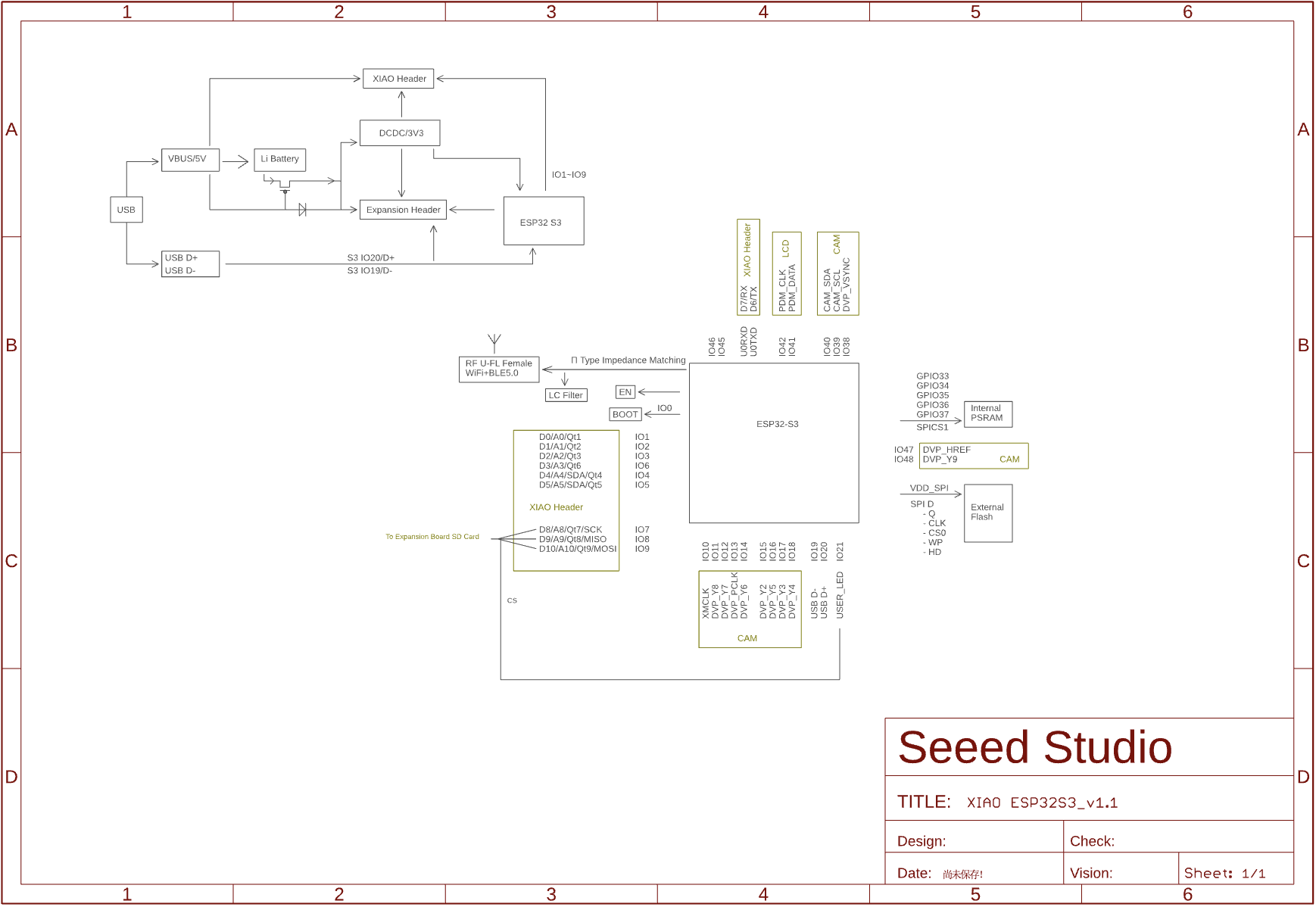
Introduction of Xiao ESP32S3 board:
The Xiao ESP32S3 is a development board based on the ESP32-S3 chip, which is a high-performance, low-power microcontroller with integrated Wi-Fi and Bluetooth connectivity.
It has a built-in 8M PSRAM & 8MB Flash, which makes it ideal for embedded applications requiring high performance and low power consumption.
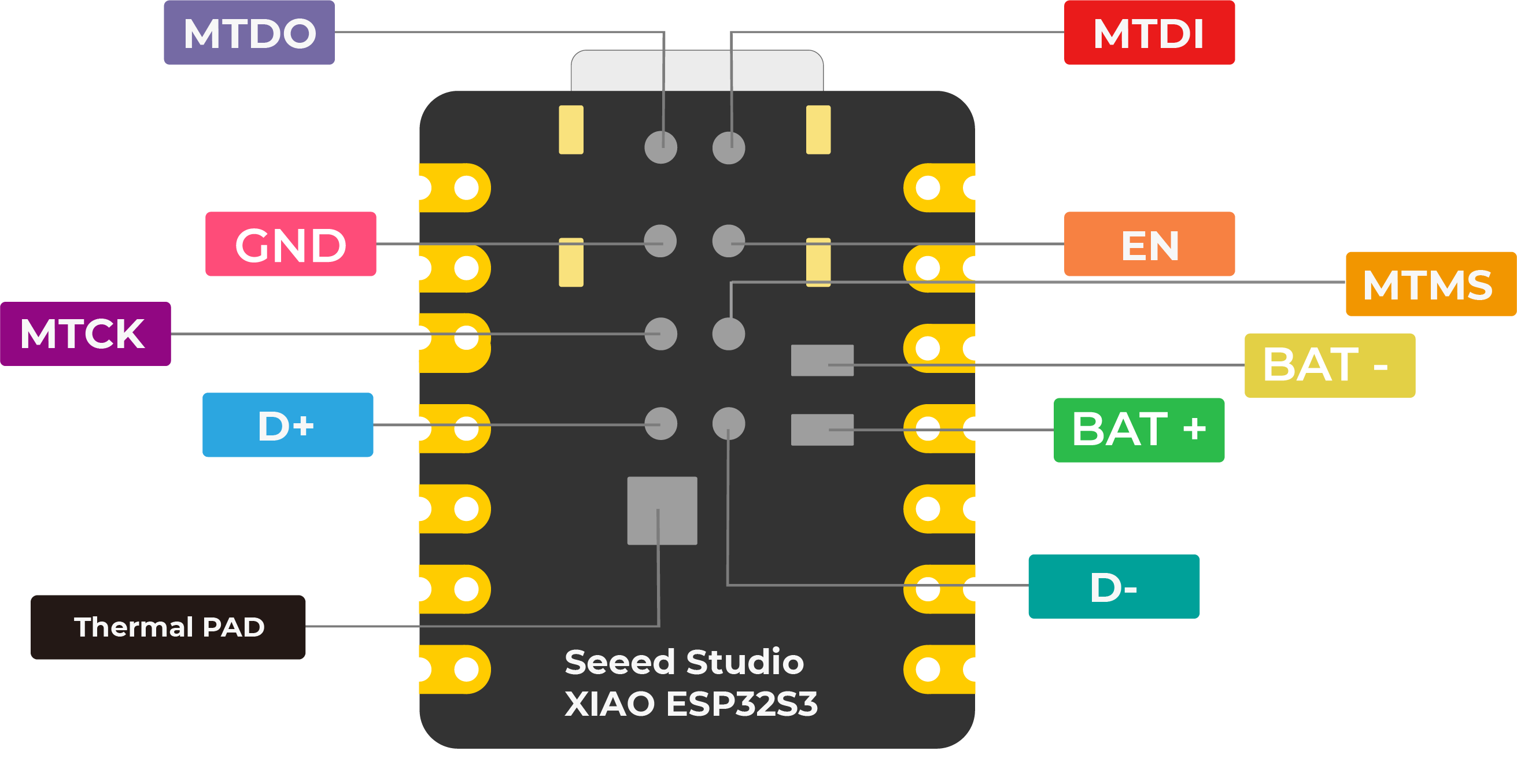
Powerful MCU Board:
Incorporate the ESP32S3 32-bit, dual-core, Xtensa processor chip operating up to 240 MHz, mounted multiple development ports, Arduino / MicroPython supported
Advanced Functionality (for Sense):
Detachable OV2640 camera sensor for 1600*1200 resolution, compatible with OV5640 camera sensor, integrating additional digital microphone
Elaborate Power Design:
Lithium battery charge management capability, offers 4 power consumption models which allow for deep sleep mode with power consumption as low as 14μA
Great Memory for More Possibilities:
Offers 8MB PSRAM and 8MB FLASH, supporting SD card slot for external 32GB FAT memory
Outstanding RF Performance:
Support 2.4GHz Wi-Fi and BLE dual wireless communication, support 100m+ remote communication when connected with U.FL antenna
Thumb-sized Compact Design:
21 x 17.5mm, adopting the classic form factor of XIAO, suitable for space-limited projects like wearable devices
Programmed My Xiao ESP32S3 board to interact and communicate:
To program my Xiao ESP32S3 board for local interaction and remote communication, I followed several steps using the Arduino IDE.
Here’s a detailed guide on how I accomplished this:
1. Setting Up the Arduino IDE
I first made sure my Arduino IDE was prepared to handle the Xiao ESP32S3:
- Installed the Arduino IDE from here
- Added ESP32 board support:
- Opened the Arduino IDE, went to File > Preferences.
- Entered the following URL into the **Additional Board Manager URLs: ESP32-S3
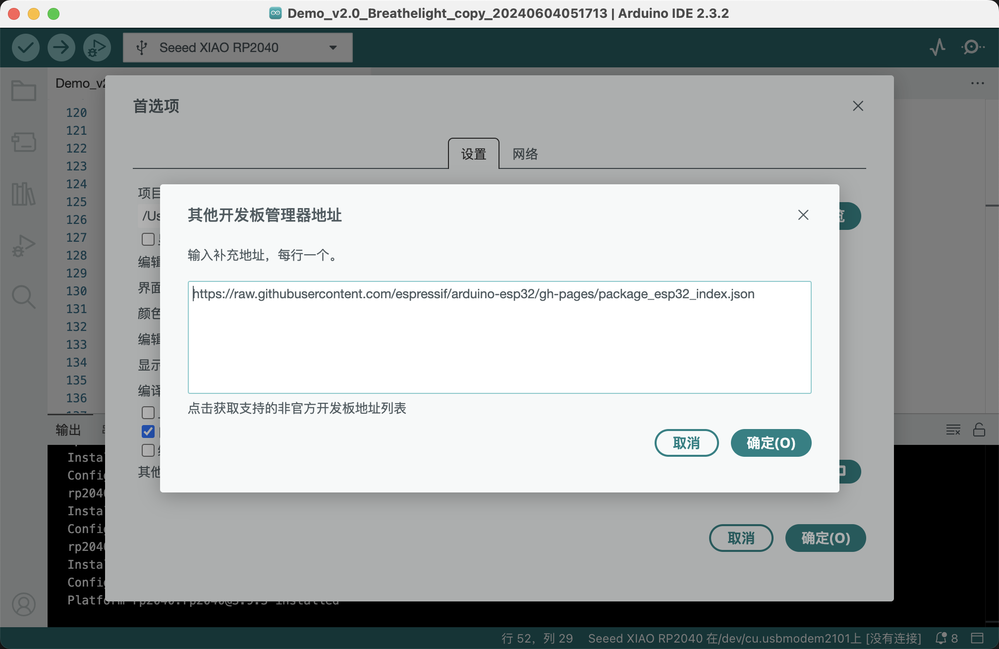
- Finished setting up the board support.
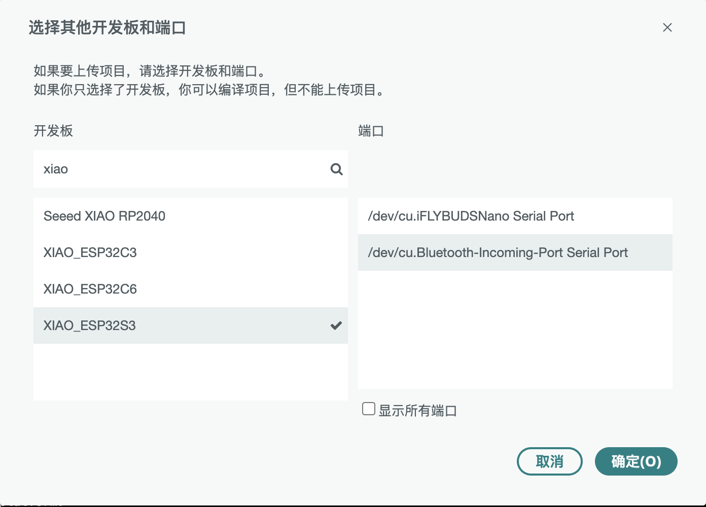
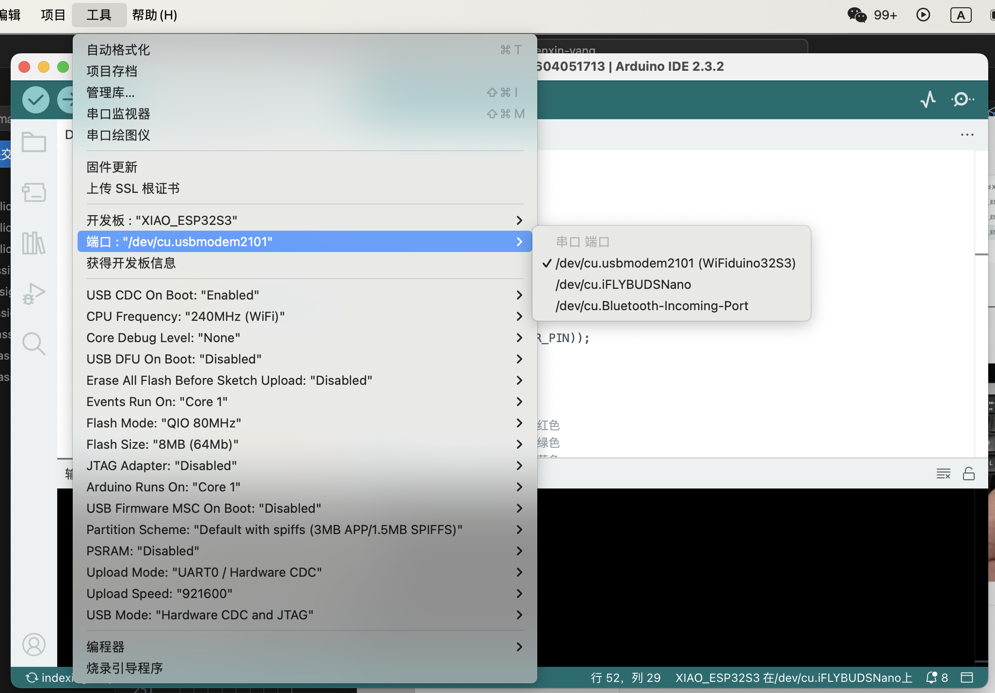
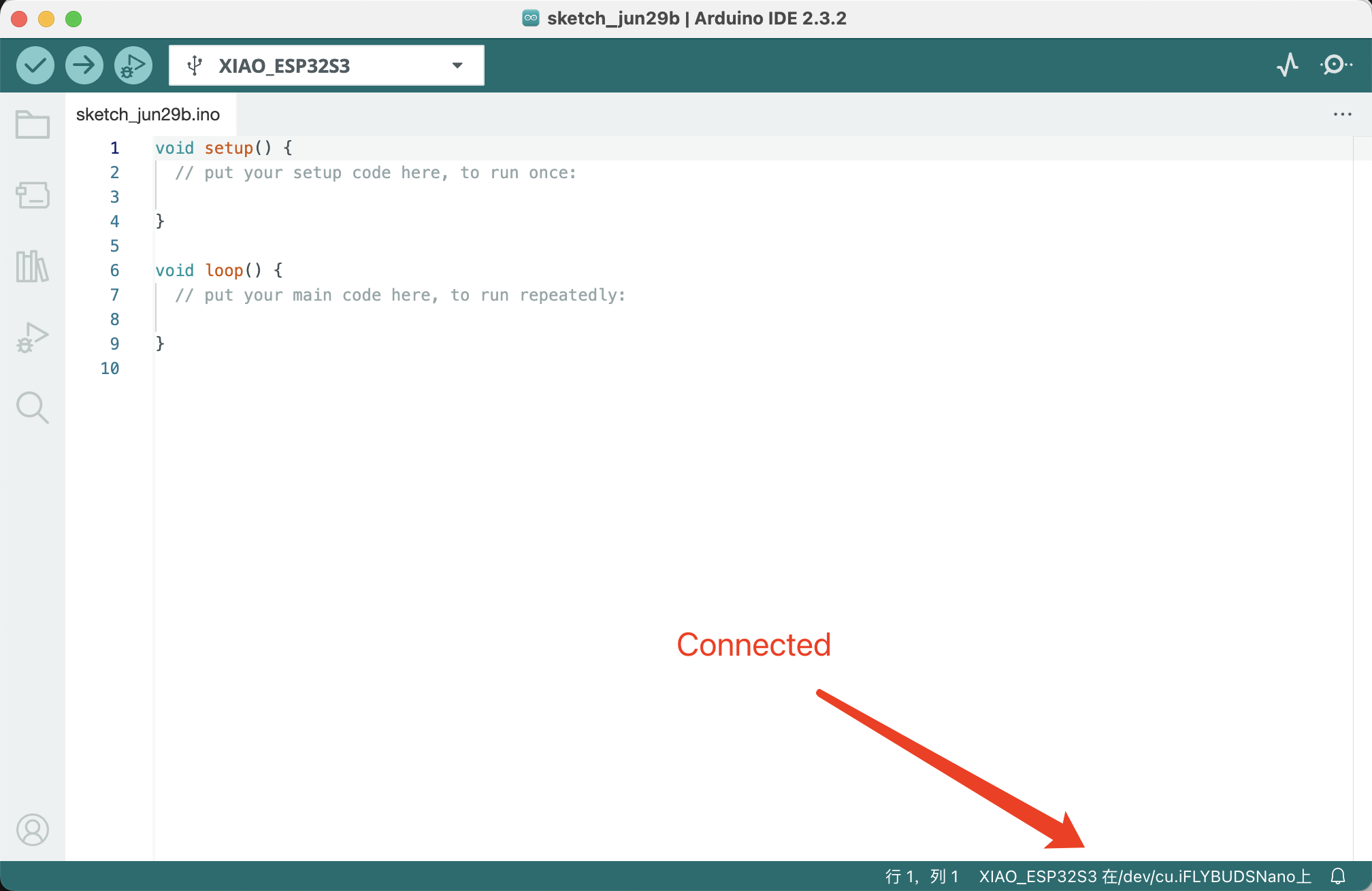
2. Connecting My Xiao ESP32S3 to Arduino IDE
- I connected my Xiao ESP32S3 to my computer using a micro USB cable.
- Selected my board from Tools > Board and chose the appropriate board type (e.g., ESP32S3 Dev Module).
- Chose the COM port that the board was connected to under Tools > Port.
3. Using a blink program to test connectivity.b>
I used the blink without delay program to test the connectivity of my Xiao ESP32S3 board.

My LED is connected to the third pin, so I adjusted the Blink program accordingly.
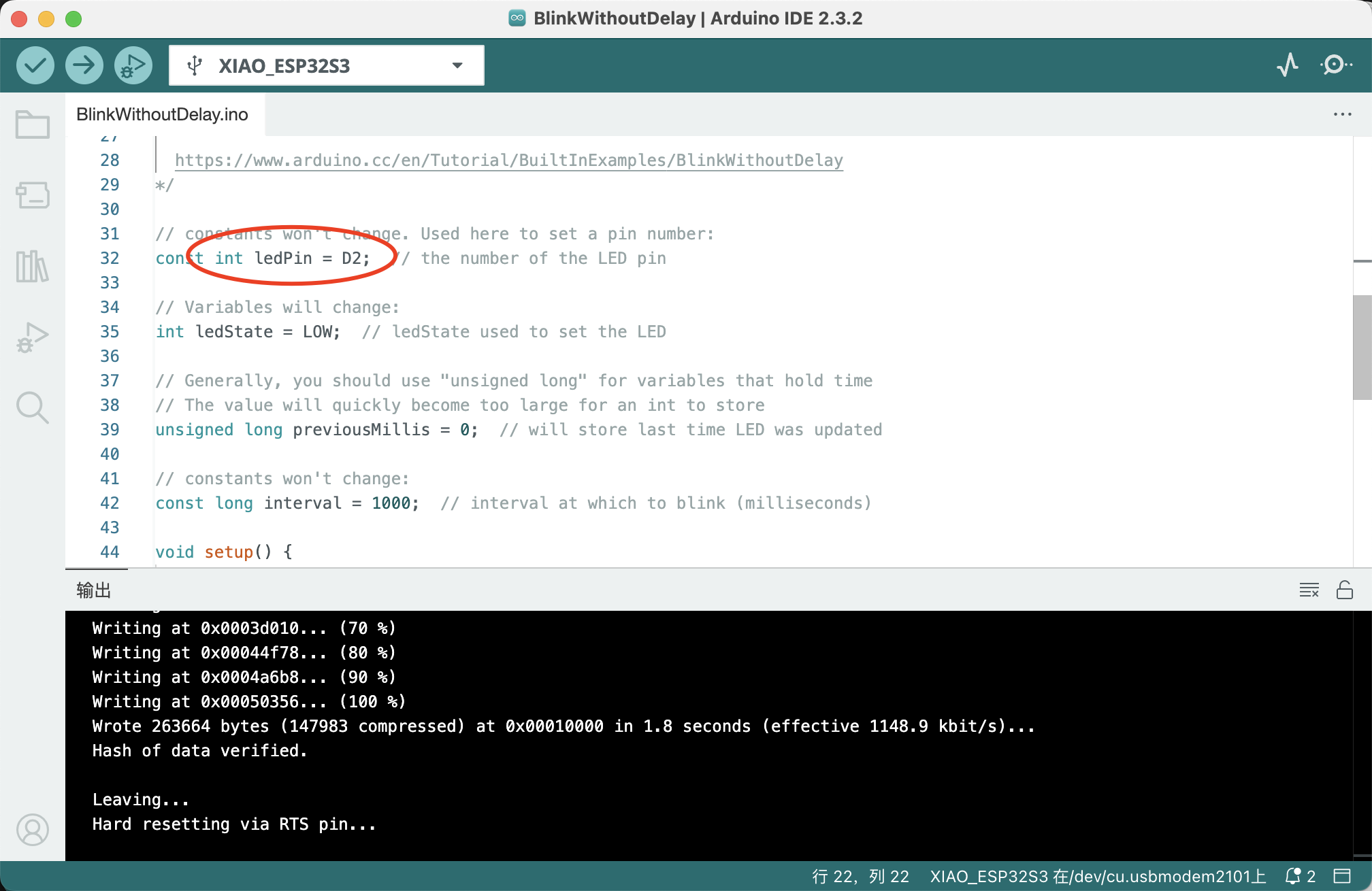
I uploaded the program to my Xiao ESP32S3 board and verified that the LED blinked.
Here is my code:
  const int ledPin = LED_BUILTIN;  // the number of the LED pin

  // Variables will change:
  int ledState = LOW;  // ledState used to set the LED

  // Generally, you should use "unsigned long" for variables that hold time
  // The value will quickly become too large for an int to store
  unsigned long previousMillis = 0;  // will store last time LED was updated

  // constants won't change:
  const long interval = 1000;  // interval at which to blink (milliseconds)

  void setup() {
    // set the digital pin as output:
    pinMode(ledPin, OUTPUT);
  }

  void loop() {
    // here is where you'd put code that needs to be running all the time.

    // check to see if it's time to blink the LED; that is, if the difference
    // between the current time and last time you blinked the LED is bigger than
    // the interval at which you want to blink the LED.
    unsigned long currentMillis = millis();

    if (currentMillis - previousMillis >= interval) {
      // save the last time you blinked the LED
      previousMillis = currentMillis;

      // if the LED is off turn it on and vice-versa:
      if (ledState == LOW) {
        ledState = HIGH;
      } else {
        ledState = LOW;
      }

      // set the LED with the ledState of the variable:
      digitalWrite(ledPin, ledState);
    }
  }
3.The programming processes & code
Communication with XiaoESP32 can be achieved through the Serial Monitor in the Arduino IDE.
I modified the code above to record the number of LED blinks through serial communication.
Here is the modified code:
  const int ledPin = LED_BUILTIN;  // the number of the LED pin

  // Variables will change:
  int ledState = LOW;  // ledState used to set the LED
  unsigned long previousMillis = 0;  // will store last time LED was updated
  unsigned long blinkCount = 0;  // count of how many times the LED has blinked

  // constants won't change:
  const long interval = 1000;  // interval at which to blink (milliseconds)

  void setup() {
    // set the digital pin as output:
    pinMode(ledPin, OUTPUT);
    // start serial communication at 9600 baud:
    Serial.begin(9600);
  }

  void loop() {
    // here is where you'd put code that needs to be running all the time.

    // check to see if it's time to blink the LED; that is, if the difference
    // between the current time and last time you blinked the LED is bigger than
    // the interval at which you want to blink the LED.
    unsigned long currentMillis = millis();

    if (currentMillis - previousMillis >= interval) {
      // save the last time you blinked the LED
      previousMillis = currentMillis;

      // if the LED is off turn it on and vice-versa:
      if (ledState == LOW) {
        ledState = HIGH;
        blinkCount++;  // increment blink counter when LED turns on
      } else {
        ledState = LOW;
      }

      // set the LED with the ledState of the variable:
      digitalWrite(ledPin, ledState);

      // print the blink count to the serial monitor:
      Serial.print("Blink count: ");
      Serial.println(blinkCount);
    }
  }

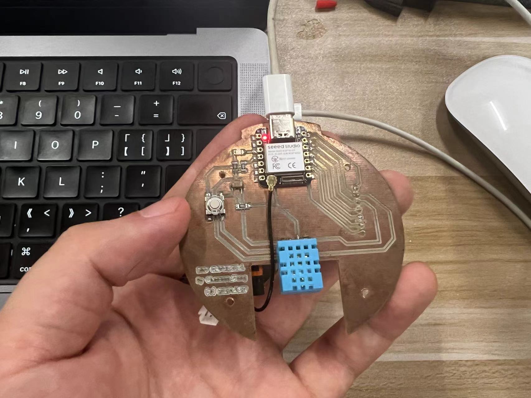
4.Hero shots
Here is the "Hero shots video" of the blink program running on my Xiao ESP32S3 board :
Team Assignment
Group Assignment link.Browse through the datasheet for your microcontroller
Here is the datasheet for the Xiao ESP32S3 board:
Xiao ESP32S3 Datasheet

Compare the performance and development workflows for other architectures.
Xiao RP2040
Microcontroller:
The RP2040 is designed by Raspberry Pi Foundation. It features:
• Dual-core ARM Cortex M0+ processor running at up to 133 MHz.
• 264 KB of SRAM.
• No built-in WiFi or Bluetooth.
Development Environment:
• Primarily programmed using C/C++ in the Arduino IDE or Pico SDK (official development platform by Raspberry Pi).
• Supports MicroPython and CircuitPython, which can be easier for beginners or for rapid prototyping.
Performance Aspects:
• The dual-core processor allows for multitasking within applications, which can be an advantage in scenarios where concurrent processes must be managed.
• Lacks connectivity features, which means external modules are necessary for IoT applications.
Development Workflow:
• Development is straightforward with documentation from Raspberry Pi.
• The board is well-supported in community forums and by extensive learning resources, especially in educational contexts.
Xiao ESP32S3
Microcontroller:
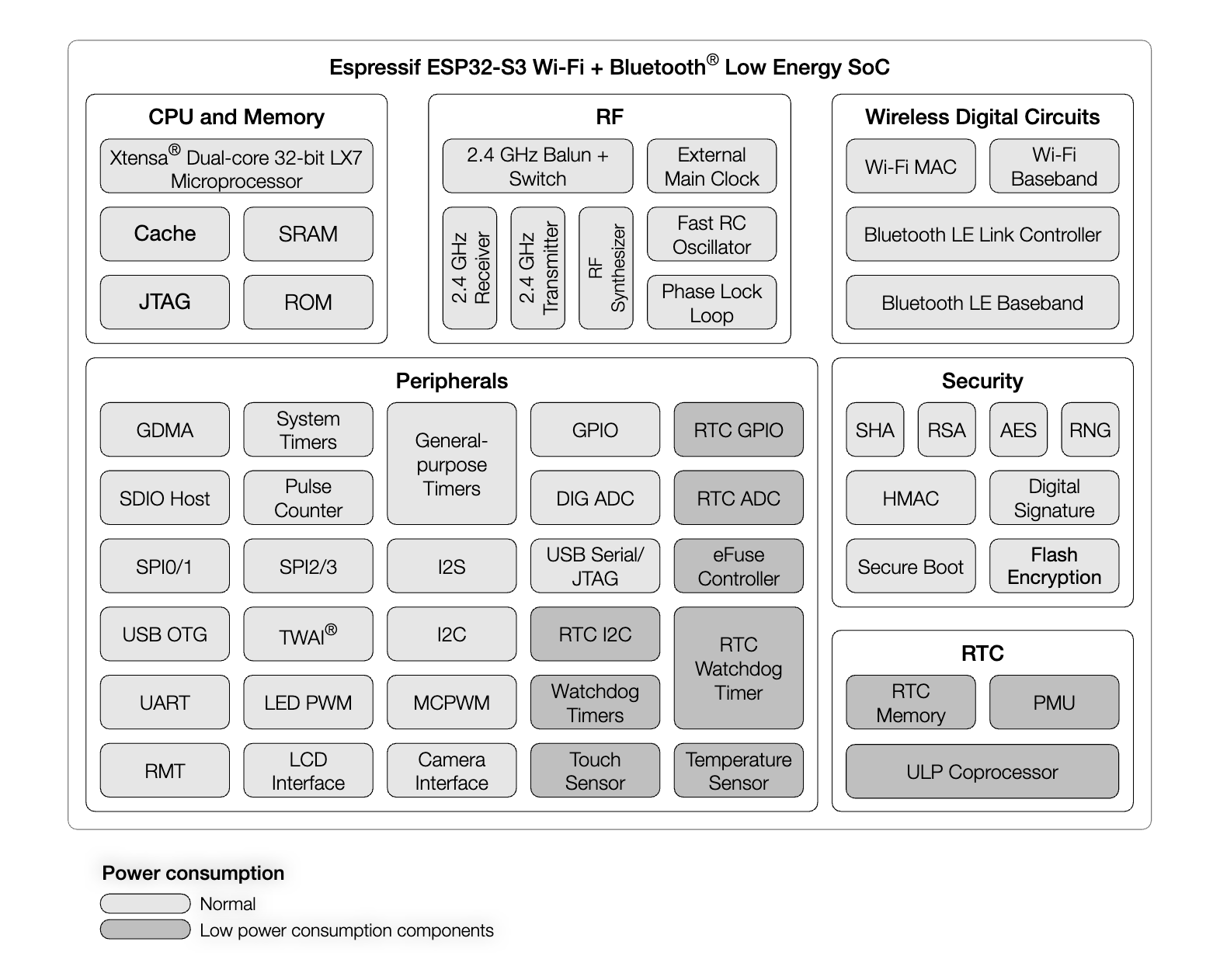
The ESP32S3 is designed by Espressif Systems. It features:
• Dual-core 32-bit LX7 processor running at up to 240 MHz.
• 512 KB of SRAM, and additional 384 KB of ROM.
• Built-in WiFi and Bluetooth 5 (LE) capabilities.
Development Environment:
• Supports development using the Arduino IDE, Espressif IDF, and other high-level languages like Python and JavaScript via frameworks like MicroPython and Espruino.
• Offers advanced features like secure boot and cryptographic hardware acceleration which are essential for secure IoT applications.
Performance Aspects:
• The higher clock speed and additional memory make it suitable for more complex applications involving web servers, networking, and multimedia.
• Integrated WiFi and Bluetooth greatly enhance its capabilities for IoT projects, allowing for easy integration into smart home systems, wearable tech, and more.
Development Workflow:
• While it offers more advanced features, the complexity of the development environment can be higher. Espressif IDF, though powerful, has a steeper learning curve compared to Arduino IDE.
• Extensive documentation is available, and the community support is robust due to the popularity of ESP32 chips.
Comparison Summary
• Performance: The ESP32S3 generally offers higher performance due to its faster processor, larger memory, and integrated wireless capabilities. It’s more suitable for applications requiring connectivity and higher data processing capabilities.
• Ease of Use: The RP2040 might be easier for beginners to start with, especially with the simplicity of the Pico SDK and Arduino IDE, but lacks the built-in connectivity that the ESP32S3 provides.
• Development Tools and Community Support: Both boards are well-supported with tools and communities. However, the ESP32S3 may offer more in terms of versatility due to its support for various programming environments and its built-in networking features.
• Application Suitability: Choose RP2040 for basic projects, educational purposes, or where dual-core processing of standalone tasks is required without the need for built-in network connectivity. Opt for ESP32S3 in projects demanding complex computing needs, internet connectivity, and advanced IoT applications.
Let's Jump to the Top !!!